- 您现在的位置:买卖IC网 > Sheet目录255 > SZMSQA6V1W5T2G (ON Semiconductor)TVS ARRAY QUAD ESD 6.6V SOT353
�� �
�
�MSQA6V1W5T2G,� SZMSQA6V1W5T2G�
�MAXIMUM� RATINGS�
�Rating�
�Peak� Power� Dissipation� @� 20� m� s�
�@T� A� ?� 25� ?� C� (Note� 1)�
�Steady� State� Power� ?� 1� Diode� (Note� 2)�
�Thermal� Resistance�
�Junction� ?� to� ?� Ambient�
�Above� 25� ?� C,� Derate�
�Maximum� Junction� Temperature�
�Operating� Junction� and� Storage� Temperature� Range�
�ESD� Discharge�
�MIL� STD� 883C� ?� Method� 3015� ?� 6�
�IEC1000� ?� 4� ?� 2,� Air� Discharge�
�IEC1000� ?� 4� ?� 2,� Contact� Discharge�
�Lead� Solder� Temperature� (10� s� duration)�
�Symbol�
�P� pk�
�P� D�
�R� q� JA�
�T� Jmax�
�T� J� T� stg�
�V� PP�
�T� L�
�Value�
�150�
�385�
�325�
�3.1�
�150�
�?� 55� to� +150�
�16�
�16�
�9�
�260�
�Unit�
�W�
�mW�
�?� C/W�
�mW/� ?� C�
�?� C�
�?� C�
�kV�
�?� C�
�Stresses� exceeding� Maximum� Ratings� may� damage� the� device.� Maximum� Ratings� are� stress� ratings� only.� Functional� operation� above� the�
�Recommended� Operating� Conditions� is� not� implied.� Extended� exposure� to� stresses� above� the� Recommended� Operating� Conditions� may� affect�
�device� reliability.�
�1.� Non� ?� repetitive� current� per� Figure� 5.� Derate� per� Figure� 10.�
�2.� Only� 1� diode� under� power.� For� all� 4� diodes� under� power,� P� D� will� be� 25%.� Mounted� on� FR� ?� 4� board� with� min� pad.�
�See� Application� Note� AND8308/D� for� further� description� of� survivability� specs.�
�ELECTRICAL� CHARACTERISTICS�
�(T� A� =� 25� ?� C� unless� otherwise� noted)�
�I�
�Symbol�
�I� PP�
�V� C�
�Parameter�
�Maximum� Reverse� Peak� Pulse� Current�
�Clamping� Voltage� @� I� PP�
�I� F�
�I� R� V� F�
�V� RWM�
�I� R�
�V� BR�
�Working� Peak� Reverse� Voltage�
�Maximum� Reverse� Leakage� Current� @� V� RWM�
�Breakdown� Voltage� @� I� T�
�V� C� V� BR� V� RWM�
�I� T�
�V�
�I� T�
�I� F�
�Test� Current�
�Forward� Current�
�V� F�
�P� pk�
�C�
�Forward� Voltage� @� I� F�
�Peak� Power� Dissipation�
�Capacitance� @� V� R� =� 0� and� f� =� 1.0� MHz�
�I� PP�
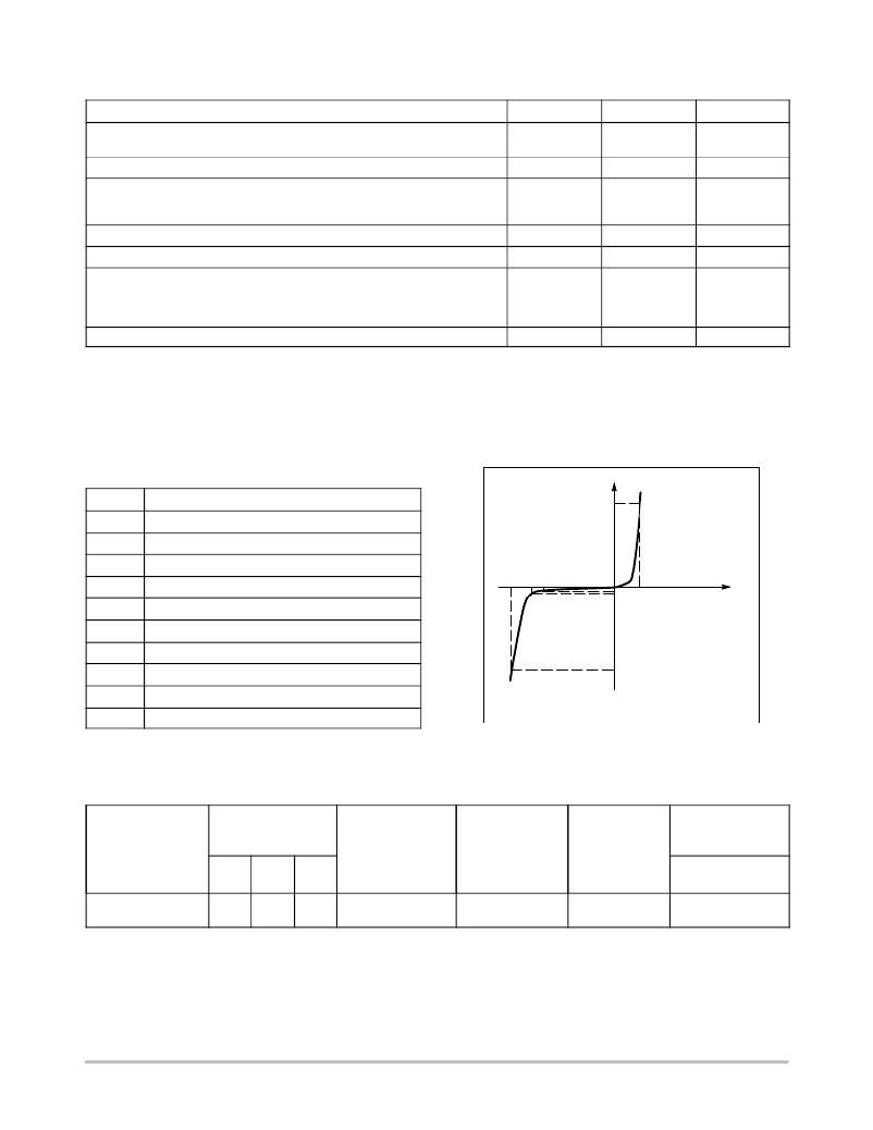
�Uni� ?� Directional� TVS�
�*See� Application� Note� AND8308/D� for� detailed� explanations� of�
�datasheet� parameters.�
�ELECTRICAL� CHARACTERISTICS�
�Breakdown� Voltage�
�Device*�
�V� BR� @� 1� mA� (Vo)�
�(Note� 3)�
�Min� Nom� Max�
�Leakage� Current�
�I� RM� @� V� RWM� =� 3� V�
�(� m� A)�
�Capacitance�
�@� 0� V� Bias�
�(pF)�
�Max�
�V� F� @� I� F� =� 200�
�mA�
�(V)�
�V� C�
�Per� IEC61000� ?� 4� ?� 2�
�(Note� 4)�
�MSQA6V1W5T2G�
�6.1�
�6.6�
�7.2�
�1.0�
�90�
�1.25�
�Figures� 1� and� 2�
�See� Below�
�3.� V� BR� is� measured� with� a� pulse� test� current� I� T� at� an� ambient� temperature� of� 25� ?� C.�
�4.� For� test� procedure� see� Figures� 3� and� 4� and� Application� Note� AND8307/D.�
�*Include� SZ-prefix� devices� where� applicable.�
�http://onsemi.com�
�2�
�发布紧急采购,3分钟左右您将得到回复。
相关PDF资料
SZNUP2105LT3G
IC CAN BUS PROTECTOR DUAL SOT-23
SZNUP4016P5T5G
TVS ARRAY ULT LOW CAP SOT-953
SZNUP4301MR6T1G
IC TVS DIODE ARRAY 70V 6-TSOP
SZP6SMB62AT3G
TVS ZENER 600W 62V UNIDIR SMB
SZSM05T1G
TVS ZENER DUAL 300W 5V ESD SOT23
SZSMF12CT1G
TVS ARRAY 5LINE 100W 12V SC88
SZSMF14AT1G
TVS ZENER 200W 14V SOD123FL
T28/M
TERMINAL MINI .062"HOLE 1000/PKG
相关代理商/技术参数
SZ-MT2
制造商:Fuji Electric 功能描述:
SZ-MT5
制造商:Fuji Electric 功能描述:
SZ-MZ1
制造商:Fuji Electric 功能描述:
SZN-002T-P0.7K
制造商:JST Manufacturing 功能描述: 制造商:JST Manufacturing 功能描述:CONTACT CRIMP RECEPTACLE 28-26AWG 制造商:JST Manufacturing 功能描述:28-26 AWG 0.8-1.1 Insulation O.D 9mm) SZN Series Contact 制造商:JST Manufacturing 功能描述:CONTACT, CRIMP, RECEPTACLE, 28-26AWG, Series:SZN, For Use With:SZN Series 1.5mm 制造商:JST Manufacturing 功能描述:SZN crimp contact 28-26 awg
SZN-003T-P0.7K
制造商:JST Manufacturing 功能描述: 制造商:JST Manufacturing 功能描述:SZN crimp contact 30-28 awg
SZ-N11J
制造商:Fuji Electric 功能描述:
SZ-N11T
制造商:Fuji Electric 功能描述:
SZ-N1J
制造商:Fuji Electric 功能描述: